Web-based Voltage and Thermocouple Data Logger from DATAQ Instruments.
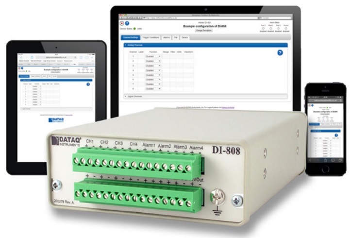
The DI-808 has a built-in web server which allows you to access, configure, manage, and oversee all aspects of the instrument’s measurement in real time. The Ethernet interface allows integration with any existing local area network (LAN) or virtual private network (VPN.) Using the internet via simple port forwarding allows remote access from any location.
8 analogue input channels feature channel-independent voltage and thermocouple configurations. Voltage measurements support ±10 mV to ±50 V measurements across twelve programmable ranges. Thermocouple configurations support J, K, T, B, R, S, E, and N types. Full channel isolation allows virtually any measurement in tough industrial environments, such as: grounded thermocouples, powered thermocouples, off-ground current shunts, as well as unexpected and unknown ground potential differences.
Complementing the analogue input channels are 4 pulse inputs. Each input can be independently programmed for simple state detection, to operate as a counter, or make a frequency measurement. These allow you to acquire various data types such as volume data from a flow sensor (count), and flow rate (frequency.) Other examples include rpm measurements or simple counting in production or product life test applications.
Both analogue and pulse measurements are synchronously reported in the same sampling interval, and all measurements are time-and-date-stamped. Program sampling intervals as often as once every 25 mS or as infrequently as once every hour, with 18 selectable intervals in between. There’s even an external option to synchronize sampling to external events.
The DI-808 also includes 4 alarm output channels that you can use to flag exceptions during a recording. Each discrete output can be used to signal a PLC, turn on an alarm, or otherwise used as demanded by the application. Each alarm output is also linked to the web interface, where an email alert (or text alert, if supported by your provider) can be triggered when the alarm activates.
Analogue Inputs |
||
| Number of Channels: | 8 | |
| Configuration: | Differential, Isolated | |
| Isolation: | Input-to-output, channel-to-channel | |
| Programmable measurements per channel: | Voltage, Thermocouple | |
|
Programmable thermocouple types and measurement range per channel: Over 25 ±3 °C ambient temperature range. |
||
| Thermocouple Type | Temperature Measurement Range (°C) | Accuracy (°C) |
| J | -190 to 1200 | ±(0.1% of span + 2) |
| K | -180 to 1360 | ±(0.1% of span + 2) |
| T | -190 to 400 | ±(0.1% of span + 1) |
| B | 600 to 1000 1001 to 1810 |
±(0.2% of span + 4) ±(0.1% of span + 3) |
| R | -40 to 300 301 to 1760 |
±(0.2% of span + 6) ±(0.1% of span + 3) |
| S | -40 to 400 401 to 1750 |
±(0.2% of span + 6) ±(0.1% of span +3) |
| E | -160 to 990 | ±(0.1% of span + 1) |
| N | -170 to 50 51 to 1290 |
±(0.1% of span + 3) ±(0.1% of span + 1) |
| Programmable voltage measurement ranges per channel: | ±10 mV, ±25 mV, ±50 mV, ±100 mV, ±250 mV, ±500 mV, ±1 V, ±2.5 V, ±5 V, ±10 V, ±25 V, ±50 V | |
| Voltage measurement accuracy: At 25 °C ambient temperature. Following 30 minutes warm-up. Excluding common mode error. |
±(0.05% of range + 10 µV) | |
| Input impedance: | 1 MΩ, all ranges | |
| Absolute maximum input without damage: | 120 V (±dc or rms) | |
| Maximum common mode voltage: | 120 V (±dc or rms) | |
| Min common mode rejection (330Ω unbalance): | >110 dB (DC to 60 Hz) | |
| Channel-to-channel crosstalk rejection: (Rsource ≤ 330 Ω; Freqsource ≤ 60 Hz) | > 110 dB | |
| Alarm and trigger hysteresis: | Voltage: ±0.5% of the full scale range Temperature: ±0.3 °C |
|
Digital/Pulse Inputs |
||
| Number of Channels: | 4 | |
| Pull-up value: | 4.7 KΩ | |
| Isolation: | None | |
| Input high voltage threshold: | 1.8 V minimum | |
| Input low voltage threshold: | 1.4 V maximum | |
| Absolute voltage input without damage: | 0 ≤ V ≤ 30 V | |
| Maximum count value: | 232 - 1 (.csv format) 65,535 (WinDaq format) |
|
| Maximum measured frequency: | >100 kHz (.csv format) 65,565 Hz (WinDaq format) |
|
Alarm Outputs |
||
| Number of channels: | 4 | |
| Maximum drain voltage: | 30 V | |
| Maximum sink current: | 100 mA | |
ADC Characteristics |
||
| Voltage Measurement Resolution: | ||
| Range | Resolution | |
| ±10 mV | 305 nV | |
| ±25 mV | 763 nV | |
| ±50 mV | 1.52 µV | |
| ±100 mV | 305 µV | |
| ±250 mV | 763 µV | |
| ±500 mV | 15.3 µV | |
| ±1 V | 30.5 µV | |
| ±2.5 V | 76.3 µV | |
| ±5 V | 152.6 µV | |
| ±10 V | 305 µV | |
| ±25 V | 763 µV | |
| ±50 V | 1.53 mV | |
| Thermocouple Temperature Measurement Resolution: | ||
| TC Type | Resolution | |
| J | 0.086 °C | |
| K | 0.096 °C | |
| T | 0.037 °C | |
| B | 0.096 °C | |
| R/S | 0.111 °C | |
| E | 0.073 °C | |
| N | 0.092 °C | |
| 4-20 mA current loop resolution: | 26,214 ADC counts over the 4-20 mA range (±5 VFS range with 250-Ω shunt resistor) | |
| Programmable sampling intervals: | 25, 50, 100, 250, 500 mS 1, 2, 5, 10, 20, 30 S 1, 2, 5, 10, 20, 30 minutes 1 hour, External |
|
Internal Memory |
||
| Type: | Non-volatile flash | |
| Size: | 32 GB | |
| Use: | Automatic backup of recorded data | |
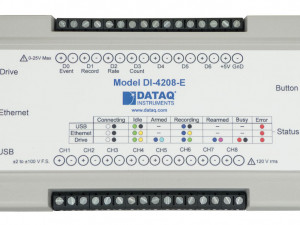
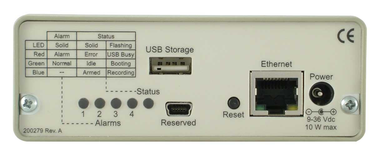
Indicators and Controls |
||
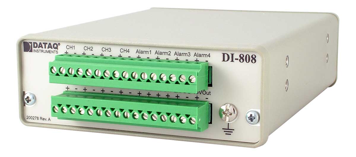
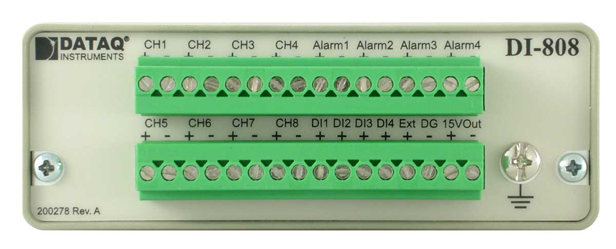
| Signal I/O: | Dual, removable 16-position screw terminal connectors | |
| Power connector: | 2.0 mm centre pin, 5 mm shell | |
| Status light: | One multicolour LED indicating status | |
| Alarm lights: | 4 multicolour LEDs | |
| Ethernet interface connector: | RJ45 | |
| USB drive receptacle: | Type A male | |
| USB connector: | Mini B style (usage is reserved) | |
| Control button: | Push type to set device operating mode | |
| Ground: | Screw terminal to establish Earth ground. | |
Power I/O |
||
| Input power requirements: | 9-36 V dc @ 7.5 Watts 9-36 V dc @ 10 Watts (w/excitation) |
|
| Excitation power supply output: | 15 V, 130 mA max, 13 mA min | |
Environmental |
||
| Operating Temperature: | 0 to 70 °C | |
| Storage Temperature: | -20 to 70 °C | |
| Storage Humidity: | 0 to 90% non-condensing | |
Physical Characteristics |
||
| Enclosure: | All-metal. Steel top, aluminium base | |
| Mounting: | Desktop; bulkhead with optional brackets | |
| Dimensions: | 13.81D × 10.48W × 3.81H cm | |
| Weight: | 453 grams | |
Configurable Components |
||
| Network variables: | IP address, Subnet mask, Gateway, DNS | |
| Account log-on information: | For FTP, SFTP, SMB, SMTP | |
| User log-on information: | User and administrator names and passwords | |
Supported Standards |
||
| Network Time Protocol (NTP): | Syncs internal time and date clock to Internet time | |
| File Transfer Protocol (FTP): | Allows the instrument to push re-corded data to an FTP server | |
| Secured File Transfer Protocol (SFTP): | Allows the instrument to push re-corded data to an SFTP server | |
| Server Message Block (SMB) protocol: | Allows the instrument to record data to a local server drive | |
| Simple Mail Transfer Protocol (SMTP): | Allows the instrument to send data and alarms to multiple email addresses | |
Display Subsystem |
||
| Digital display: | Numeric display of acquired values scaled into engineering units in real time. Selectable precision of 1 to four digits to the right of the decimal point. | |
| Waveform display: | Scrolling plot of selected channel data in real time versus time of day. | |
| Alarms status: | Virtual LEDs display the status of the four alarm outputs | |
Channel Settings Subsystem |
||
| Analogue channel configuration: | Voltage and measurement range, temperature and thermocouple type, moving average filter, engineering units, channel label | |
| Digital/pulse channels: | Discrete, count, count with reset, frequency, engineering units, channel label | |
Trigger Subsystem |
||
| Start or stop recording trigger conditions: | Level: Above/below level, In/out window Alarm: Upon alarm activation Date/time: Specific date and time. Daily selection External |
|
| Auto rearm: | Enabled or disabled | |
Alarm Subsystem |
||
| Level or edge selection: | Level: Alarm is activated when alarm condition is met on first encounter Edge: Alarm is activated only after first not being met. |
|
| Analog/pulse channel levels: | Above/below level, In/out window | |
| Thermocouple burnout: | Any burnout detected on a Thermocouple channel | |
| Selectable alarm ports: | 1-4 | |
| Alarm hold: | Enable/disable | |
File Subsystem |
||
| File browse/download: | Browse files on the DI-808 internal flash memory or connected USB drive and allow selectable down-loads to the client device. | |
| Format local file storage: | Formats internal flash memory, erasing previously recorded files and reallocating file space for new recorded data. | |
| Get local file space: | Returns the available file space. | |
| Base file name: | Allows recorded files to be assigned a definable file name, and to option-ally have date and time appended. | |
| File type: | Allows the recorded file format to be defined as either ASCII CSV or binary WDH. | |
Device Subsystem |
||
| Device settings and information: | Program device sampling interval, temperature units (°F/°C), enable or disable auto start on boot feature, time/date/ synched to connected PC or NTP server, reboot device. | |
| Network configuration: | Configure device IP address, DNS, Subnet mask, Gateway. | |
| Users and accounts: | Configure user and administrator names and passwords. | |