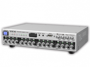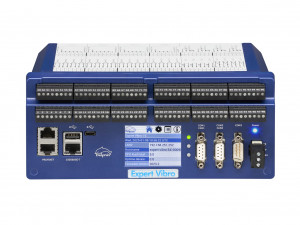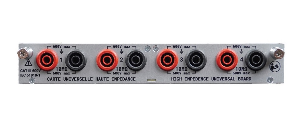
High Impedance Module for DAS1800 from B&K Precision and Sefram Instruments.
Configure the DAS1800 to fit your needs with any combination of modules up to 10.
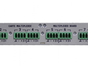
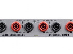
| Universal | High Impedance | Multiplexed | |
| Channels | 4 | 4 | 8 |
| Maximum Voltage | ± 600 VDC | ± 600 VDC | ± 48 VDC |
| RMS Voltage | 424 VRMS | 424 VRMS | – |
| Resolution | 16 bit | 16 bit | 18 bit |
| Sampling Rate | 1 MSa/s/ch | 1 MSa/s/ch | 5 kSa/s |
| Input Impedance | 1 MΩ | 10 MΩ | 2 MΩ |
| Input Type | Single ended | Single ended | Differential |
| Isolation | Yes | Yes | No |
| Voltage | Yes | Yes | Yes |
| Current | Yes | Yes | Yes |
| Thermocouples | Yes | Yes | Yes |
| RTDs | No | No | Yes |
| Frequency | Yes | Yes | No |
| Counter | Yes | Yes | Yes |
| PWM | Yes | Yes | No |
| Number of Channels | 4 | |
| Input Type | Isolated single ended input - 4mm Banana Plug | |
| Max. Input Voltage | ± 600 VDC or 424 Vrms | |
| Range | 19 Ranges: ± 500 μV / 1 mV / 2.5 mV / 5 mV / 10 mV / 25 mV / 50 mV / 100 mV / 250 mV / 500 mV / 1 V / 2.5 V / 5 V / 10 V / 25 V / 50 V / 100 V / 250 V / 600 V |
|
| DC Accuracy *1 | ≤ ± 25 mV | ± 0.1% of full range + 10 μV *2 |
| ± 25 mV to ± 500 mV | ± 0.1% of full range + 10 μV | |
| ≥ ± 1 V | ± 0.06% of full range | |
| Offset Drift | ± 50 ppm/°C ± 1 μV/°C | |
| Input Impedance | 10 MΩ for ranges ≥ ± 1 V, 25 MΩ for ranges ≤ ± 0.5 mV | |
| Input Capacitance | 150 pF | |
| Intrinsic Noise *3 (standard deviation in % of the span) |
≤ ± 1 mV | < 0.2% |
| ± 2.5 mV to ± 10 mV | < 0.1% | |
| ± 25 mV to ± 500 mV | < 0.05% | |
| ≥ ± 1 V | < 0.05% | |
| CMRR | ≤ ± 500 mV | > 85 dB |
| ≥ ± 1 V | > 70 dB | |
| Crosstalk | > -90 dB | |
| Isolation | CH to CH and CH to GND, > 100 MΩ at 650 VDC | |
| Safety | CAT III 600 V | |
| Bandwidth | ≤ ± 2.5 mV | 1 kHz |
| ± 5 mV to ± 25 mV | 10 kHz | |
| ± 50 mV to ± 500 mV | 60 kHz | |
| ≥ ± 1 V to ± 10 V | 20 kHz | |
| ≥ ± 25 V | 80 kHz |
| ADC | 16 bit – SAR | |
| Sampling Interval | 1 μs (1 MSa/s) each channel | |
| Compute Frequency | 4 ms | |
| Cold Junction | Uncompensated, internal, external (other channel) | |
| Accuracy *4: ± 1.25°C | ||
| Type | J | -210 °C to 1200 °C |
| K | -250 °C to 1370 °C | |
| T | -200 °C to 400 °C | |
| S | -50 °C to 1760 °C | |
| B | 200 °C to 1820 °C | |
| E | -250 °C to 1000 °C | |
| N | -250 °C to 1300 °C | |
| R | -50°C to 1768°C | |
| Threshold | Set by user, auto | |
| Duty Cycle | 10% minimum – (minimum pulse width, 20 μs) | |
| Counter | 48 bits | |
| Frequency | 0.1 Hz to 100 kHz | |
| Accuracy: 0.01% reading, 0.1 Hz to 10 Hz 0.05% reading, 10 Hz to 100 kHz |
||
| PWM | Absolute error: 0.1% from 0.1 Hz to 1 kHz 0.5% from 1 kHz to 5 kHz |
|
| Compute Period | Compute on the 1 Ms/s data flow Each period until 100 Hz 10 ms between 100 Hz and 10 kHz |
|
| Accuracy (Sine wave ≥ 1 V) |
10 Hz to 2 kHz | ± 0.1% of full range |
| 2 kHz to 10 kHz | ± 0.3% of full range | |
| Current | Through shunt or clamp | |
| Sensor | 0 to 10 V, 4 to 20 mA (with external shunt), duty cycle or frequency sensor, other user defined settings | |
| Calculations | Min – max – avg on Δt | |
Note: All specifications apply to the unit after a temperature stabilization time of 30 minutes over an ambient temperature range of 23 °C ± 5 °C.
(*1) Direct measure taken on DMM at 10 (50 Hz) / 12 (60 Hz) NLPC (200 ms) and full bandwidth
(*2) Only when offset adjustment has been performed after installing a new module. Otherwise accuracy is ± 0.1% of full range + 20 μV
(*3) Measure ± short circuit termination to 50 Ω on chassis during 1 sec at the fastest acquisition speed and full bandwidth
(*4) Only when cold junction adjustment has been performed after installing a new module. Otherwise accuracy is ±3 °C