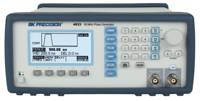
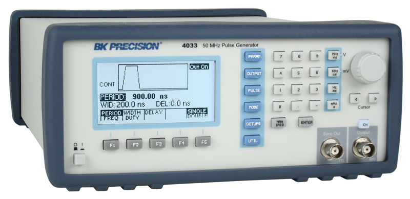
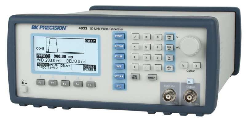
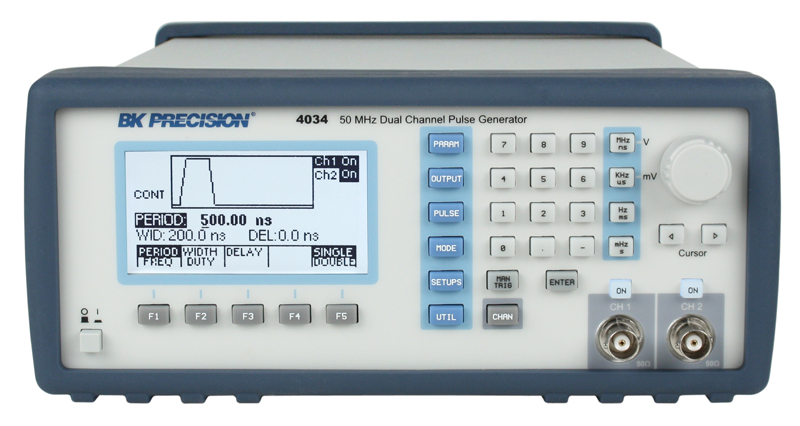
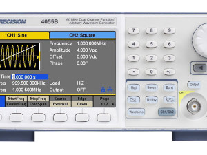
BK4033 & BK4034 50 MHz Pulse Generators
High performance programmable pulse generators for testing digital systems and circuits based on TTL, CMOS, or ECL technologies.
SKU
BK4033 & BK4034
Category Signal Generators
Manufacturer: B&K
Call for price
Description
50 MHz Pulse Generators from B&K Precision.
The BK4033 and BK4034 are high performance programmable pulse generators for testing digital systems and circuits based on TTL, CMOS, or ECL technologies. These instruments generate clean and accurate pulses at up to 6 digits resolution with a repetition rate up to 50 MHz, variable pulse widths from 10 ns to 10 s, and pulse delays from 0 ns to 10 s. Output levels are adjustable from -10 V to +10 V, with pulse amplitudes settable from 0.1 Vpp to 10 Vpp into a 50 ohm load. All parameters, modes, and functions are programmable via the front panel or remote control commands. Additionally, the pulse generators provide selectable complementary pulse and double pulse generation in continuous, triggered, gated, and counted burst modes.
Product Features
- Repetition rate of 0.1 Hz to 50 MHz
- Dual channel operation (BK4034 only): Both channels offer full functionality and all parameters such as pulse width and transition time can be set independently. Channels can be synchronized with with the push of a button
- Flexible trigger modes: Continuous, Triggered (internal, external, manual), Gated Burst and External Width
- Pulse width programmable from 10 ns to 10 s
- Transition times (rise and fall times) variable from 6 ns to 25 ms
- Programmable delay and double pulse
- Store up to 99 different test setups with auto retention of last power down setup
- 10 Vpp into 50 ohm output
- Closed case calibration
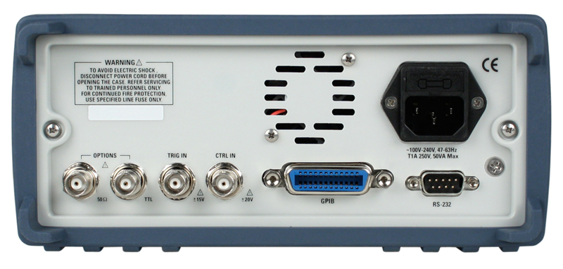
- Programmable via GPIB and RS-232
- SCPI compatible
- 3 year warranty
Applications
- Automatic Test Equipment (ATE)
- Avionics and radar testing
- Switching power supply testing
- Characterization of active components
For more information, please see the Overview Video.
The specifications describe the instrument performance after 30 minutes warm-up period into a 50 Ω load. All timing characteristics are measured at 50% of
amplitude with fastest edges.
| Model |
BK4033 |
BK4034 |
|
| Channels | 1 | 2 | |
| Frequency | 0.1 Hz to 50 MHz | ||
Timing Characteristics |
|||
| Period | Range | Single Pulse: 20 ns to 10 s (50 MHz to 0.1 Hz repetition rate) Double Pulse: 40 ns to 10 s (25 MHz to 0.1 Hz repetition rate) |
|
| Resolution | Up to 6 digits, limited to 100 ps | ||
| Accuracy | ±0.01 %1 | ||
| Jitter | < 0.01 % of setting +20 ps on Period, Width and Delay | ||
| Width | Range | 10 ns to (Period – 10 ns) | |
| Resolution | Up to 6 digits, limited to 100 ps | ||
| Accuracy | ±(0.5% of setting +500 ps) | ||
| Double Pulse | ±(0.5% of setting +3 ns) for the second pulse | ||
| Delay | Range | 0 ns to (Period – Width – 10 ns) | |
| Resolution | Up to 6 digits, limited to 100 ps | ||
| Accuracy | ±(0.5% of setting +500 ps) | ||
| Duty Cycle | Range | 1 to 99% | |
| Resolution | 3 digits (0.1%) | ||
| Accuracy | Limited by width and pulse accuracy | ||
Output Characteristics |
|||
| Amplitude | High Level Range | -9.90 V to +10 V into 50 Ω load (-19.80 V to +20 V into open circuit) |
|
| Low Level Range | -10 V to +9.90 V into 50 Ω load (-20 V to +19.80 V into open circuit) |
||
| Amplitude Range | 0.1 V to 10 V p-p into 50 Ω load (20 V p-p max into open circuit) |
||
| Resolution | 3 digits limited to 10 mV | ||
| Accuracy | ±1% of setting ±10 mV into 50 Ω | ||
| Aberrations | <5% + 20 mV into 50 Ω load, for pulse levels between ±5V | ||
| Output Resistance | 50 Ω | ||
| Offset Accuracy | ±1% ±25 mV | ||
Operating Modes |
|||
| Continuous | Output continuous at programmed period rate | ||
| Triggered | Output quiescent until triggered by an internal, external, GPIB or manual trigger, then generates one cycle at programmed period rate | ||
| Gated | Same as triggered mode except pulses are output for the duration of the gated signal. The last cycle started is completed | ||
| Burst | Same as triggered mode for programmed number of cycles from 2 to 999,999 as set by the N-BURST function | ||
| External Width | Trigger duration and rate sets pulse width and repetition | ||
Pulse Functions |
|||
| Single | One pulse at each selected period up to 50 MHz repetition rate | ||
| Double | One pair of pulses at each period up to 25 MHz repetition rate. Both pulses have the same selected width; the position of the second pulse set by the delay control. | ||
Transmission Times |
|||
| Range | <6 ns to 100 ms variable. Leading and trailing edges settable separately and limited to 20:1 ratio between settings into one of the following ranges: 5 ns-100 ns; 50 ns-1.0 us; 500 ns-10 us; 5.0 us-100 us; 50 us-1.0 ms; 500 us-10 ms, 5 ms – 100 ms |
||
| Resolution | 3 digits limited to 10 ps | ||
| Accuracy | ±(5% of setting +2 ns) | ||
| Linearity | <5% deviation from a straight line between 10% and 90% points, for transitions > 50 ns | ||
Internal Trigger |
|||
| Range | 100 ns to 100 s | ||
| Resolution | 4 digits limited to 100 ns | ||
| Accuracy | ±0.01% | ||
Trigger Input and Output |
|||
| Sensitivity | 200 mVpp minimum | ||
| Minimum Width | 10 ns | ||
| Maximum Rate | 50 MHz | ||
| Input Impedance | 10 kΩ | ||
| Input Protection | ±15V DC plus peak AC | ||
| Range | Selectable from -10 V to +10 V | ||
| Resolution | 3 digits limited to 10 mV | ||
| Slope Selection | Positive or Negative | ||
| Sync Output | A TTL level pulse at the programmed period. Output impedance is 50 Ω, protected against short circuit and up to ±15 V accidental input. The high level is >2 V into 50 Ω and with 3.5 ns typical transition times. | ||
Remote Programming |
|||
| Interface | GPIB and RS-232, IEEE-488.2 and SCPI compatible | ||
| GPIB Function Codes | SH1, AH1, T6, L4, SR1, RL1, PP0, DC1,DT1, C0, E2 | ||
General |
|||
| Memory | Non-volatile, stores up to 99 complete panel settings. Last user setup also retained at power down. | ||
| Power Requirements | 100-240 V, ±10%, 48-66 Hz, 50 VA maximum | ||
| Dimensions WxHxD | 213 x 300 x 88 mm | ||
| Net Weight | 3 Kg | ||
| EMC | Conforms to EN55011 class B for radiated and conducted emissions | ||
| Electrical Discharge Immunity | Conforms to EN55082 | ||
| Safety Specifications | Conforms to EN61010, CE Approved | ||
| Operating Temperature | 0 °C to 50 °C | ||
| Storage Temperature | -20 °C to 60 °C | ||
| Humidity | 0 °C to 30 °C | ||
| Included Accessories | AC Power cord, CD containing instruction manual, RS-232 cable, test report and certificate of calibration | ||
1 Applies to values entered when incremented frequency or decrementing period, entering values differently than described will typically be less accurate.

