40MHz, 80MHz and 120MHz Dual Channel Function Waveform Generators from B&K Precision.
The BK4060B Series Dual Channel Function/Arbitrary Waveform Generators are capable of producing precise sine, square, triangle, pulse, and arbitrary waveforms. This series combines the cost saving benefits of both DDS and true point-by-point arbitrary architectures to meet a wide range of applications that require high signal fidelity and low jitter arbitrary waveform generation capabilities.
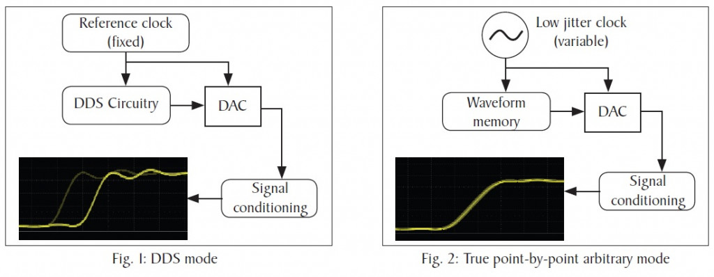
The BK4060B Series arbitrary waveform generator (AWG) architecture can be toggled between conventional DDS or true arbitrary mode. Compared to DDS (Fig. 1), true point-by-point AWG implementation offers improved signal integrity by producing lower jitter and less distortion (Fig. 2). All models are capable of generating 16-bit waveforms up to 300 MSa/s in DDS or 75 MSa/s in true arbitrary mode.
With an easy-to-read colour display and intuitive user interface with numeric keypad, these instruments offer plenty of features including linear / logarithmic sweep, burst mode, and variable DC offset. Generate custom arbitrary waveforms using the application software included, or select from the 196 built-in arbitrary waveforms.
For more information, please see the below video.
Note: All specifications apply to the unit after a temperature stabilization time of 30 minutes over an ambient temperature range of 23 °C ± 5 °C.
| Model |
BK4062B |
BK4063B |
BK4064B |
| Channels | 2 | ||
Frequency Characteristics |
|||
| Sine | 1 μHz to 40 MHz | 1 μHz to 80 MHz | 1 μHz to 120 MHz |
| Square | 1 μHz to 25 MHz | ||
| Triangle / Ramp | 1 μHz to 1 MHz | ||
| Pulse | 1 μHz to 25 MHz | ||
| Gaussian Noise (-3 dB) | > 120 MHz | ||
| Arbitrary | 1 μHz to 20 MHz | ||
| Accuracy | ± 1 ppm (1 year) | ||
| Resolution | 1 μHz | ||
Arbitrary Characteristics |
|||
| Built-in Waveforms | 196 | ||
| Waveform Length | 8 points to 8 M points | ||
| Vertical Resolution | 16 bits | ||
| Sampling Rate | 300 MSa/s (DDS mode) 75 MSa/s (true arbitrary mode) |
||
| Minimum Rise/Fall Time (typical) |
4.5 ns (DDS mode) 8.5 ns (true arbitrary mode) |
||
| Jitter (rms) | < 150 ps (1 Vpp, into 50 Ω load, true arbitrary mode) | ||
| Non-volatile Memory Storage |
80 MB file system | ||
Output Characteristics |
|||
| Amplitude Range(1) (into open circuit) |
2 mVpp to 20 Vpp ( ≤ 20 MHz) 2 mVpp to 10 Vpp ( > 20 MHz) |
||
| Amplitude Resolution | Up to 4 digits | ||
| Amplitude Accuracy (10 kHz, 0 V offset) |
± (1% + 1 mVpp) | ||
| Amplitude Flatness (reference to 10 kHz Sine, 2.5 Vpp) |
± 0.3 dB (50 Ω load, DC to 100 MHz) ± 0.4 dB (50 Ω load, 100 MHz to 120 MHz) |
||
| Cross Talk | < -60 dBc (between channels) | ||
| Offset Range (DC) | ± 5 V (into 50 Ω load) ± 10 V (into open circuit) |
||
| Offset Resolution (DC) | Up to 4 digits | ||
| Offset Accuracy (DC) | ± (1% + 2 mV), into open circuit | ||
| Output Impedance (typical) |
50 Ω | ||
| Output Protection | Overvoltage (see user manual for details) | ||
Waveform Characteristics |
|||
| Harmonic Distortion (sine, 0 dBm input, typical) |
DC to 10 MHz, < -65 dBc 10 MHz to 20 MHz, < -60 dBc 20 MHz to 40 MHz, < -55 dBc 40 MHz to 60 MHz, < -50 dBc 60 MHz to 80 MHz, < -45 dBc 80 MHz to 100 MHz, < -40 dBc 100 MHz to 120 MHz, < -38 dBc |
||
| Total Harmonic Distortion (sine) |
< 0.075% (10 Hz to 20 kHz at 0 dBm) | ||
| Spurious (non-harmonic) |
≤ 50 MHz, -70 dBc max. > 50 MHz, -65 dBc max. |
||
| Rise/Fall Time (square) | < 9 ns (10% to 90% at 1 Vpp, into 50 Ω load) | ||
| Variable Duty Cycle (square) |
0.001% to 99.999% (depending on frequency setting) | ||
| Jitter (rms) Cycle to Cycle (square) |
150 ps (1 Vpp, into 50 Ω load, typical) | ||
| Ramp Symmetry | 0% to 100% | ||
| Ramp Linearity | < 1% of peak output (triangle, ramp at 1 kHz, 1 Vpp, 100% symmetry) | ||
Pulse |
|||
| Pulse Width | 16.3 ns minimum | ||
| Rise / Fall Time | 8.4 ns to 22.4 s (1 Vpp, 10% to 90%, into 50 Ω load) | ||
| Duty Cycle Range | 0.001% to 99.999% (depending on frequency setting) | ||
| Overshoot | < 3% (100 kHz, 1 Vpp) | ||
| Jitter (rms) Cycle to Cycle |
150 ps (1 Vpp, into 50 Ω load) | ||
Burst |
|||
| Waveform | Sine, square, ramp, pulse, arbitrary, noise | ||
| Type | Cycle (1 to 1,000,000 cycles), infinite, gated | ||
| Start / Stop Phase | 0º to 360º | ||
| Internal Period | 1 μs to 1000 s | ||
| Gated Source | Internal, external trigger | ||
| Trigger Source | Internal, external, manual | ||
Phase Offset |
|||
| Range | -360º to 360º | ||
| Resolution | 0.1º | ||
AM, FM & PM Modulation Characteristics |
|||
| Carrier(2) | Sine, square, ramp, arbitrary | ||
| Source | Internal, external | ||
| Modulation Waveform | Sine, square, ramp, noise, arbitrary | ||
| AM Modulation Depth | 0% to 120% | ||
| FM Frequency Deviation | 0 to 0.5 x (maximum output frequency) | ||
| PM Phase Deviation | 0º to 360º | ||
ASK & FSK Modulation Characteristics |
|||
| Carrier(2) | Sine, square, ramp, arbitrary | ||
| Source | Internal, external | ||
| Modulation Waveform | 50% duty cycle square waveform | ||
DSB-AM Modulation Characteristics |
|||
| Carrier(2) | Sine, square, ramp, arbitrary | ||
| Source | Internal, external | ||
| Modulation Waveform | Sine, square, ramp, noise, arbitrary | ||
PWM Modulation Characteristics |
|||
| Source | Internal, external | ||
| Modulation Waveform(2) | Sine, square, ramp, noise, arbitrary | ||
| Internal Modulation Frequency |
1 mHz to 1 MHz | ||
Sweep Characteristics |
|||
| Waveforms(2) | Sine, square, ramp, arbitrary | ||
| Sweep Shape | Linear or logarithmic, up or down | ||
| Sweep Time | 1 ms to 500 s | ||
| Sweep Trigger | Internal, external, manual | ||
Harmonic Output Characteristics |
|||
| Maximum Order | 16 | ||
| Type | Even, odd, all | ||
Auxiliary Input / Output |
|||
| Sync Out | TTL compatible(4) Output impedance: 100 Ω (typical) Maximum frequency: 10 MHz Minimum pulse width: 50 ns (typical) |
||
| Modulation Input | ± 12 Vpp (typical) for 100% modulation Input impedance: 10 kΩ Frequency range: 0 kHz to 50 kHz |
||
Trigger Input |
|||
| Level | TTL compatible(3) | ||
| Slope | Rising or falling, selectable | ||
| Pulse Width | > 100 ns | ||
| Impedance | > 100 kΩ | ||
| Latency | 100 ns maximum (sweep mode) 600 ns maximum (burst mode) |
||
Trigger Output |
|||
| Voltage Level | TTL compatible(4) | ||
| Pulse Width | > 500 ns | ||
| Impedance | 100 Ω (typical) | ||
| Maximum Frequency | 1 MHz | ||
Reference Clock |
|||
| Input | Frequency range: 10 MHz (typical) Minimum voltage input: 1.4 Vpp Input impedance: 5 kΩ |
||
| Output | Frequency range: 10 MHz (typical) Voltage level: 3.3 V (typical), 2 V (minimum) Output impedance: 50 Ω |
||
Frequency Counter |
|||
| Measurement | Frequency, period, positive / negative pulse width, duty cycle | ||
| Measurement Range | 100 mHz to 200 MHz (DC coupling) 10 Hz to 200 MHz (AC coupling) |
||
| Input Range | 100 mVrms to ± 2.5 V (< 100 MHz, DC coupling) 200 mVrms to ± 2.5 V (100 MHz to 200 MHz, DC coupling) 100 mVrms to 5 Vpp (< 100 MHz, AC coupling) 200 mVrms to 5 Vpp (100 MHz to 200 MHz, AC coupling) |
||
| Input Impedance | 1 MΩ (typical) | ||
| Coupling | AC, DC, HF REJ (≥ 250 kHz filter) | ||
Environmental and Safety |
|||
| Temperature | Operating: 0 °C to 40 °C Storage: -20 °C to 60 °C |
||
| Humidity | < 30 °C, ≤ 90 % RH 40 °C, ≤ 50 % RH |
||
| Altitude | Operating: below 3,048 m Storage: below 15,000 m |
||
| Electromagnetic Compatibility | EMC Directive 2014/30/EU, EN61326-1:2013 | ||
| Safety | Low voltage directive (LVD) 2014/35/EU, EN61010-1:2010 | ||
General |
|||
| Display | 4.3” TFT colour (24-bit) LCD touch screen | ||
| I/O Interfaces | USBTMC device, LAN, USB host port | ||
| Storage Memory | 10 instrument settings | ||
| AC Input | 100 to 240 VAC ± 10 %, 50/60 Hz 100 to 120 VAC ± 10 %, 400 Hz |
||
| Power Consumption | 50 W maximum | ||
| Dimensions (W x H x D) |
260.3 x 107.2 x 295 mm | ||
| Weight | 3.43 Kg | ||
| Warranty | 3 years | ||
| Standard Accessories | AC power cord, user manual (downloadable), USB type A-to-B cable, BNC coaxial cable, certificate of calibration | ||
| Optional Accessories | USB-to-GPIB adapter | ||
(1) This specification will be divided by 2 while applied to a 50 Ω load.
(2) Modulation schemes not available in DC mode.
(3) VIH = 2 V to 5.5 V, VIL = 0.5 V to 0.8 V
(4) VOH = 3.8 V (IOH = -8 mA), VOL = 0.44 V (IOL = 8 mA)